Blog 6 (Project Development)
- Axrega Axrega
- Feb 17, 2023
- 11 min read

Updated: Feb 19, 2023
1. Our team Chemical Device
Chemical Device: Automated Carbon Monoxide (CO) Monitoring and Ventilation System
Scenario of our problem:
During Incomplete combustion, carbon monoxide is produced. It is an odorless and colorless gas which is formed from the incomplete burning of carbon in fuels. Examples of incomplete combustion includes burning of coal, wood or any other fuel. Carbon monoxide is a harmful gas that is toxic, and when inhaled, can lead to several health problems such as headache, dizziness, weakness, stomach upset and can even cause death.
Chemical equation of Complete Combustion
Fuel + O2 ---> CO2 + H2O
Chemical equation of Incomplete Combustion
Fuel + O2 ---> CO + H2O
In parts of Vietnam, the locals are succumbing to carbon monoxide poisoning. The reason for this is the poor lifestyle of the Vietnamese locals. In some parts of Vietnam, the weather is colder and the locals tend to burn charcoal to get warmth. However most of the times, the locals tend to forget about the fire place and go to sleep without putting it off. This would produce carbon monoxide which is harmful for the locals in Vietnam.

This shows that the locals in Vietnam or other parts of the world are unaware of the dangers and production of carbon monoxide. Therefore, they usually lack a ventilation system in their homes to ventilate the air.
Therefore, we came up with our problem statement, which is:
Vietnamese people in rural areas need Carbon Monoxide detectors and ventilation systems, to prevent CO poisoning from burning coal for warmth in their homes
So, what problems does our chemical device solve?
It solves the problem of carbon monoxide in homes with poor ventilation system, by removing it with the help of a CO sensor.
Hand Sketch of Chemical Device:

2. Team Planning, Allocation and Execution
These are my team members:
Lim Yan Zhen - Chief Financial Officer (CFO)
Murugu Sundaran Jeevan (Myself) - Chief Safety Officer (CSO)
Jeremy Wong - Chief Operation Officer (COO)
Ngo Van Anh - Chief Executive Officer (CEO)
Finalised BOM table:

Finalised GANTT Chart:
Planned GANNT Chart:

Actual GANTT Chart:

Task Allocation:
Yan Zhen & Jeevan ---> CAD fusion & Laser Cutting
Van Anh & Jeremy ---> Programming and Assembly
Allocation of Roles:
Part 1. Design and Build of Rack & Pinion, Door & Stopper, and Cylinder for fan (done by Jeevan).
Documentation for task 1.
Part 2. Design and Build of Room, Stands for DC motor and Servo (done by Yan Zhen).
Documentation for task 2.
Part 3. Programming of DC motor, 360 degree servo, LED and Buzzer (done by Jeremy).
Documentation for task 3.
Part 4. Assembling of Prototype (done by Van Anh)
Documentation for task 4.
3. Design and Build Process
After completing our mid-semester exams, we began assigning tasks to each team member. Before our last CPDD practical session, we met to design the components we needed using Fusion 360, such as a hollow cylinder for the fan and a stand for the motor. During the session, we realized we needed a mechanism for our prototype, and decided gears would be the best option as we were all familiar with their mechanics. We brainstormed ways to integrate gears and came up with the idea of using a Rack and Pinion mechanism to open a gate when the CO levels in the "room" became dangerous. We decided to use a 360-degree servo to turn the gear for the gate, and Yan Zhen and I worked on designing the Rack and Pinion in Fusion 360 while Jeremy and Van Anh worked on programming the components. We printed the other components while waiting for the Rack and Pinion to finish printing.
During the second week, we continued work on the prototype by sketching the "room" in Fusion 360 and booking a laser cutting session to make the necessary pieces. While Van Anh and Jeremy continued with programming, Yan Zhen and I went to laser cut the pieces. However, we found that the pieces were too long, making the room too big, so we sketched it again and recut the pieces. Meanwhile, Van Anh and Jeremy had to solder two wires together since they were not long enough. When Yan Zhen and I returned, we realized we needed a stand for the servo and had to redo the design of the pinion.
In the third week, we glued the walls of the room together using acrylic glue and used hot glue and double-sided tape to secure the components in place. However, some components fell off due to the hot glue cooling too fast, so we had to use extra mechanical strength in some areas. The programming was also difficult as we had to have four different functions activate simultaneously when CO levels became dangerous, and the gate was inconsistent due to clearance issues between the pinion and the rack.
In the last week, we made final adjustments to the programming and discovered that programming and wiring the buzzer we bought online was actually easy. The gate was still inconsistent and loose, but we were satisfied with the results and began preparing for the CA2 presentation.
Initial Idea
This the initial function structure:

These are the rough sketches and simplified idea of how our CO detection system will work.

Initial sketch of prototype:

Final Idea
We realised that after doing our BOM and consulting with Mr Chua, had to change our set up slightly. We initially wanted a standing board for the LEDs, but we decided not to complicate things and changed it to just connect the LEDs to the breadboard. Furthermore, we needed a mechanism. Since we did not have one and lacked proper ventilation system, we decided to make a sliding door for a vent. For this, we used the mechanism of Gears. We made a rack & pinion, which resembles a sliding door with the help of a Servo to turn the gear. Hence, we needed new equipment such as servo and had to update our BOM.
We also took considerations from other fellow students in the lab on how to improve our prototype and they gave useful feedback such as orienting the motor in a different way so that the fan will run smoothly, or using a bigger shaft to connect to the servo so that it is not unstable. Taking all these constructive feedbacks, we came up with our final sketch as shown below:

Here are some pictures that we took during our building process:

3D printed parts for our CO detection system

Buzzer that we could not get from the lab and had to order

Van Anh and Jeremy soldering the wires together
Here is a video of Jeremy Soldering the wires


Yan Zhen and Jeevan laser cutting the parts for the room
Mechanism of Gear function (Rack & Pinion)
Successful attempt of our prototype with some beautiful and relaxing music

Hero Shot of our prototype
Part 1: Design & Build of Rack & Pinion, the Door & Stopper and the Cylinder for the fan
For my build and design process, I first had to do the fusion for the Rack & Pinion, the Door & Stopper and the Cylinder for the fan. So, let me walk you through the steps for the fusion and how to do them:
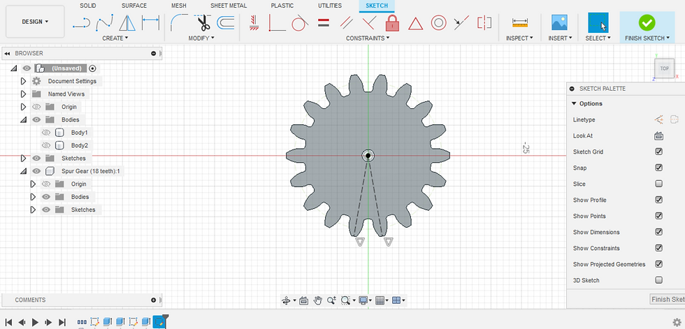
Rack & Pinion:
1. Click on the Utilities tab, and go to the Scripts and Add-ins and select "SpurGear".

2. Use a module of 1.333333 and change the number of teeth to 18. Also change the hole diameter to 2 mm and the root fillet Radius to 0.78.

3. Press "ok"

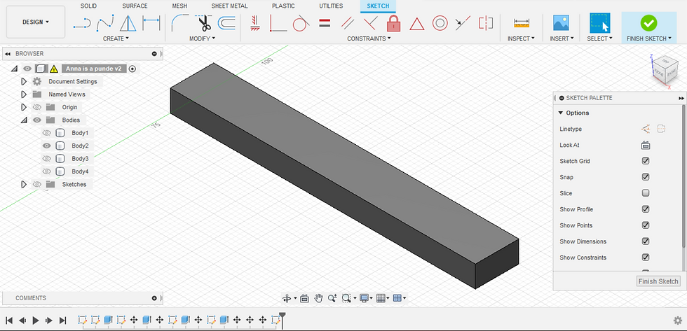
4. Create a sketch again to make the rod sticking out of the gear which is 25 mm tall.


5. Add Construction lines down the sketch.
6. Draw the border line for the teeth on the rack

7. Offset the border line for the Rack

8. Offset the sketch for Rack teeth.

9. Add the borders for the line to complete the sketch for the teeth

10. Create a Rectangle below the teeth for the rack.

11. Copy the teeth to the whole of the rectangular segment.

12. Extrude the Rack to similar height as the Gear.

13. Final Gear fusion

14. Export to .stl file for 3D printing


15. Open the file in Cura

16. Choose Ultimaker s3

17. Choose an Infill of 20%

18. Start the Slicing Process

19. Once it has sliced, we can save the file to disk and proceed to 3D printing.

Door & Stopper
1. Create a sketch of a rectangle for the Door.

2. Extrude the sketch by 2 mm

3. Create another Sketch for the stopper.

4. Extrude the stopper sketch by 5 mm
5. Export to .stl file for 3D printing


6. Open the file in Cura

7. Choose Ultimaker S3

8. Choose an Infill of 20%

9. Start the slicing process

10. Once the slicing is done, we can click on save to disk

Cylinder of Fan
1. Create a Circular Sketch of 62 mm diameter.

2. Extrude the Sketch by 50 mm

3. Create a Hole in the Cylinder to make it hollow

4. Export to .stl file for 3D printing


5. Open the file on Cura

6. Select Ultimaker S3

7. Choose an infill of 20%

8. Start the Slicing Process

9. Once the slicing is done, we can save the file to disk

Part 3. Design and Build of Room, stands for DC motor and servo (done by Yan Zhen).
Link to Yan Zhen's Blog: Yan Zhen
Part 3. Programming of DC motor, 360 degree servo, LED and Buzzer (done by Jeremy).
Link to Jeremy's Blog: Jeremy
Part 4. Assembling of Prototype (done by Van Anh)
Link to Van Anh's Blog: Van Anh
4. Problems and Solutions
In this section I will describe the problems encountered in the design and build process and
how the team solved them.
Problem 1 and how we solved it: Choosing the Mechanism for our prototype
Initially, we did not even have a mechanism for our prototype as we were unaware that it was a part of the requirement. We only realized this when Mr Chua told us about it during our practical session. We were shocked to hear this as our concept was pretty difficult to include a mechanism since we did not have any moving parts or functions. Therefore, we decided to brainstorm together and search for different mechanisms that we could use. The different mechanisms we were taught about were Actuators, Cams, Gears, Levers, Ratchets and Springs. Since we had no moving objects in our prototype, this was a big problem as we now have to think of something to add to our prototype, so that we can implement one of the mechanisms.
That was when we came across a Rack & Pinion, which used the gears mechanism. We thought of how and where we can use it, and decided to use it for a ventilation system. Our initial prototype did not have a ventilation system as we thought that we could make the fan hole act as a ventilator. Instead, we decided to change and make a separate ventilation area for our prototype. We decided to use the Rack & Pinion as sliding vent, which would open and close when CO is detected in the room. Therefore, we managed to use Gears as our mechanism.
Problem 2 and how we solved it: Extra 3mm of Acrylic being cut for the room
We realised this problem only after we had done our laser cut and when we were ready to assemble them together. When we did the fusion for the walls of the room, we failed to visualise properly how the walls would come out as. Our Acrylic walls are 3 mm thick, and we did not realise that we have to have an allowance of 3mm so that the walls sit perfectly on top of each other when glueing. Now, we the acrylic walls we have are slightly portruding out when we put them together.
To get around this, we strategically placed the acrylic walls along each other, such that the 3mm allowance and thickness does not affect when placing the top cover for the prototype. We had to slightly shift the walls and align them accordingly so that the extra 3mm of acrylic is not visible. With that, we managed to mitigate the problem of the extra 3mm of Acrylic.
Problem 3 and how we solved it: Door for vent was unstable
The door which we 3D printed kept falling down when we tried to put it along our vent hole. It was a loose piece that was not connected to anything but was leaning on one of the walls, and hence kept toppling over when the gear was used to turn the door.
We solved this problem by 3D printing a stopper and glueing it to the floor. This acted as a slot for the door to slide smoothly and prevent it from falling down. This helped the vent to function properly.
Problem 4 and how we solved it: Wires were too short
The wires provided in our arduino kit was too short to be used, as they could not reach to some of the equipments we used such as the DC motor and the servo. Furthermore, we also needed a 3 way wire for better operation of the arduino.
We solved this problem by soldering 2 wires together to make them longer. This helped us to reach the DC motor and the Servo without hindering their functions. Furthermore, we could solder 2 wires together to make a 3 way wire which was used for the Gas sensor.
5. Project Design Files as Downloadable Files
1. Rack & Pinion : Rack & Pinion .f3d & .stl
2. Door & Stopper: Door & Stopper .f3d & .stl
3. Cylinder for Fan: Cylinder for Fan .f3d & .stl
4. Servo Stand: Servo Stand .f3d & .stl
5. Motor Stand: Motor Stand .f3d & .stl
6. Wall: Wall .f3d & .dxf
7. Arduino Programming: Arduino Code
Here is the embeded version of our Prototype:
6. Below is my Learning Reflection on the overall project development:
This Project development has managed to utilise all of the things that I have learnt in the ICPD module as well as the CPDD module. I had learnt about mechanisms, Fusion 360 and 3D printing, Laser Cutting and Arduino Programming which were all used to help us create our prototype. From the overall project development, My group actually had to settle on ond idea to make our CO detection system, which was initially tough as we all had differing ideas. Therefore, we had to look for the simplest and most feasible idea to work on. Thus, we chose the CO detection system. My group managed to split the work effectively among the group members, which helped us all to complete our works on time and not having to rush them. Although there were some differing opinions on some of the ideas we implemented, we managed to sort this out as a team and work towards obtaining our end goal. Ultimately, this project development has taught me about the importance of teamwork when it comes to doing long projects as such. We each used our own strengths to our advantage, for example Jeremy and Van Anh were better at doing the Programming whereas Yan Zhen and I were better in doing the fusion and 3D printing. This actually allowed us to be more comfortable in doing the things we were better at.
Furthermore, my group always met as a whole group as we always thought that everyone should know what is going on and not be left out. Since the project development is a long and tedious process, we knew that all of the small steps and efforts we put in were crucial as it would affect the outcome in the long run. Hence, we always tried to make things as accurate or perfect as possible to avoid any problems in the future. We learnt about skills such as Triz which actually enabled us to learn and make slight improvements to our prototype. Further consultations with Mr Chua has also enabled us to come up with a smoother and aesthetic prototype which we are proud of. There were also tough times where we were unaware of what to do. For example, Jeremy struggled to make the programming for the whole prototype. He easily managed to use online resources and complete the codes required for the individual parts of the prototype such as buzzer, DC motor and the Servo. However, he could not find a way on how to operate them together. Only after multiple attempts, did he found the perfect code for all of the functions to work accordingly.
We also faced problems when it came to wiring the breadboard, as we had to use alot of wires and it tend to get tangled. There were also times where some of the wires were loosely connected or did not even work. Therefore, we had to re wire the whole breadboard multpile times to make the Arduino work. Nonetheless, we pushed on. Looking back at the project, it has actually taught me so many important qualities and skills as it has made me feel competent when using the Fusion 360 software to design things that we needed to 3D print. It has also made me much more proficient when it comes to 3D printing. We also managed to use the laser cutter, which initially I was scared of operating on my own as I was pessimistic that I would cause a fire. But, only after trying it did I realise that it wasn't so bad. I am glad that I was able to test my skills on this project development, and together with my teams help, create a wonderful prototype.
Overall, I have actually learnt so much things that I am grateful for. The whole process of ideating and designing a prototype itself was an interesting process which I believe that I have grasped an understanding of. I am also thankful for my teammates for pushing through with me during this hectic semester and completing all of our work. And finally, I am glad that our prototype turned out good and just how we expected.


Comments